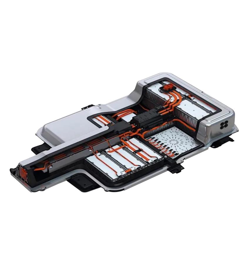
The performance, safety, and service life of electric vehicles are determined largely by the quality of their battery systems. A modern EV battery pack is not a passive energy reservoir — it is a continuously monitored, optimized, and controlled complex system. At its core sits the Battery Management System (BMS): the electronic control system that monitors, protects, and optimizes the entire pack.
Without a BMS, an electric vehicle cannot operate safely, efficiently, or durably. While the battery pack is often described as the "heart" of an EV, the BMS is the "brain" that keeps it beating correctly. This guide examines BMS architecture, core functions, thermal management strategies, topology choices, and the trajectory toward AI-enabled intelligent energy management.
EV Battery Architecture and System Complexity
Electric vehicle batteries are modular structures formed by connecting hundreds to thousands of cells in series-parallel configurations. Due to manufacturing tolerances, individual cells exhibit:
- Differing internal resistances (typically ±5–15 mΩ at cell level)
- Varying thermal behaviour under load and charge
- Non-identical charge/discharge capacity curves
This inherent heterogeneity means the pack tends toward imbalance over time. Cells age at different rates; capacity divergence grows with each cycle. Left unmanaged, the weakest cell in a series string determines the usable capacity of the entire pack — a phenomenon called the weakest-link effect. The BMS exists to counteract this at every level: measurement, balancing, thermal control, and state estimation.
Core BMS Functions
1. Monitoring
The BMS continuously acquires three classes of physical measurements across every cell or cell group in the pack:
- Voltage: Typically measured per cell to ±1–2 mV accuracy. Cell-level voltage is the primary indicator of SOC and the earliest warning of degradation.
- Current: A precision shunt or Hall-effect sensor measures pack current. Integration of current over time (Coulomb counting) is the basis of SOC estimation.
- Temperature: NTC thermistors distributed across modules — at minimum on the hottest and coldest predicted locations — feed the thermal model. Resolution of ±0.5 °C is standard for ASIL-C/D applications.
2. Protection
Protection is the safety-critical layer of the BMS. It enforces operating limits through hardware contactors and software cut-off logic:
- Overcharge protection — prevents cell voltage exceeding the upper voltage limit (e.g., 4.2 V for NMC, 3.65 V for LFP). Overcharging causes electrolyte oxidation, lithium plating, and eventually thermal runaway.
- Deep discharge protection — prevents cell voltage falling below the minimum (e.g., 2.5–3.0 V). Deep discharge causes irreversible copper dissolution at the anode.
- Overcurrent protection — limits peak discharge and charge currents to prevent dendrite formation and separator stress.
- Overtemperature protection — triggers derating or shutdown when cell temperatures exceed safe thresholds. This is the primary defence against thermal runaway propagation.
3. State Estimation
Accurate state estimation is what differentiates a sophisticated BMS from a simple protection board:
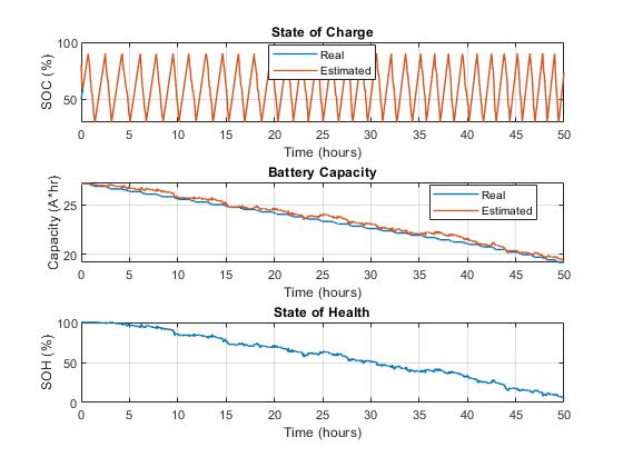
- SOC (State of Charge): The instantaneous capacity remaining, expressed as a percentage. Modern BMS implementations combine Coulomb counting with open-circuit voltage (OCV) lookup and Kalman filtering to achieve ±2–3% accuracy across temperature and age.
- SOH (State of Health): The ratio of current maximum capacity to original rated capacity. SOH degrades with cycle count and calendar ageing. Tracking SOH enables predictive replacement scheduling and second-life assessment.
- SOP (State of Power): The maximum instantaneous power the pack can deliver or accept given present SOC, temperature, and SOH. SOP feeds directly into the powertrain controller for regenerative braking limits and acceleration management.
4. Cell Balancing
Cell balancing corrects voltage divergence between cells. Two strategies exist:
- Passive balancing — dissipates excess charge as heat through bypass resistors on higher-voltage cells. Simple and low-cost; balancing currents are typically 50–200 mA. Energy is wasted.
- Active balancing — transfers charge between cells using switched-capacitor or inductor-based converters. Balancing currents of 1–5 A are achievable. Energy is redistributed rather than wasted, improving overall pack efficiency by 2–8% in high-utilization applications.
Thermal Management: The Critical Safety Layer
Temperature is the single most influential variable in battery performance, longevity, and safety. The optimal operating range for most lithium-ion chemistries is 20°C to 45°C. Outside this range, the consequences are significant:
- High temperature (>45°C): Accelerated SEI layer growth, electrolyte decomposition, and — in extreme cases — thermal runaway. Each 10°C increase above 30°C roughly halves cycle life.
- Low temperature (<10°C): Lithium-ion diffusivity in the electrolyte drops sharply. Available capacity decreases, internal resistance increases, and charging at sub-0°C conditions risks lithium plating on the anode.
The BMS manages thermal control through:
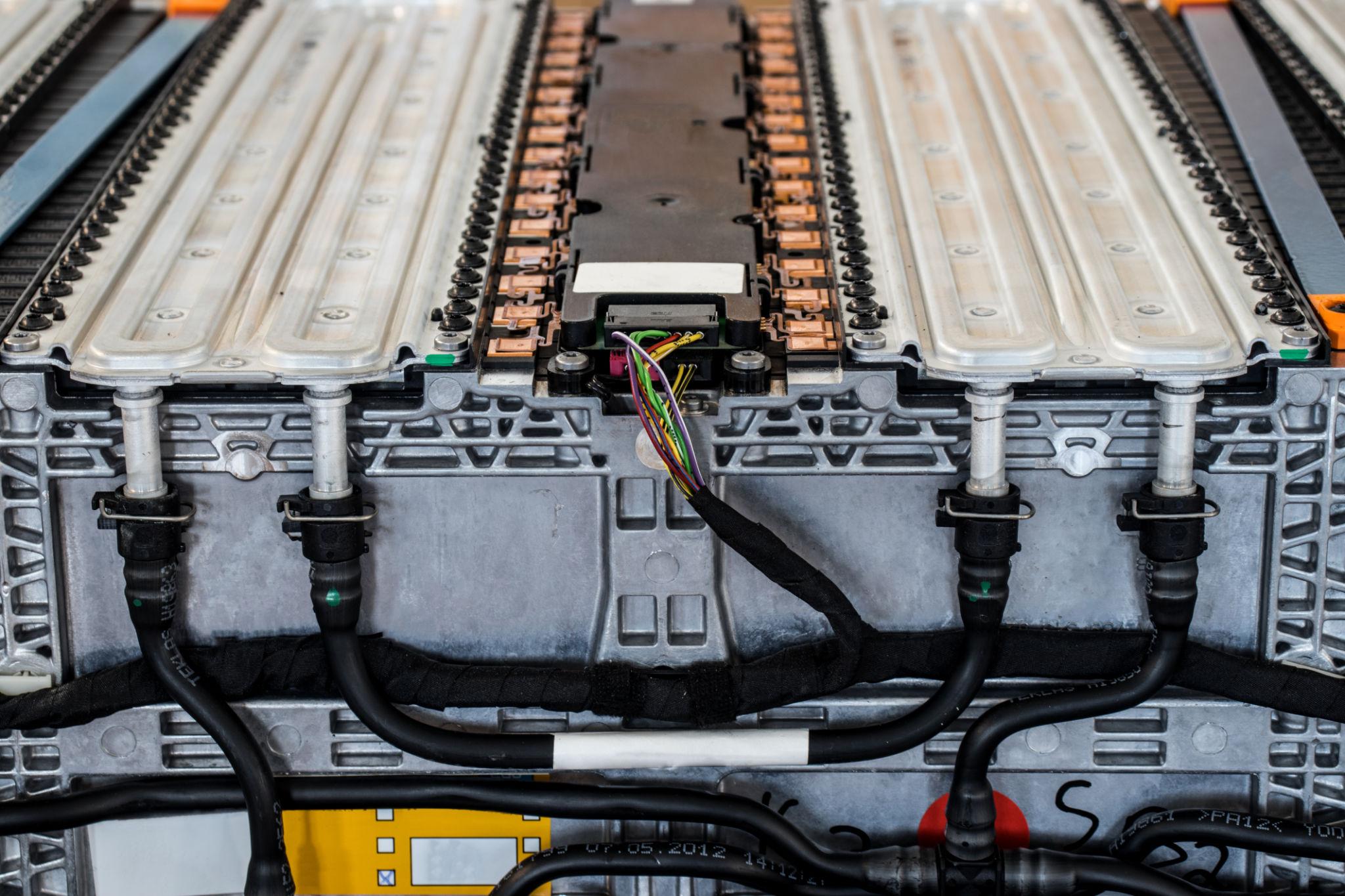
- Liquid cooling: Coolant channels (glycol-water mix) adjacent to cell surfaces. Plate-type or serpentine-channel cold plates distribute heat removal uniformly. Standard for 100+ kWh packs.
- PTC heating: Positive Temperature Coefficient heaters pre-condition the pack in cold ambient conditions before charging or high-power discharge events.
- Air cooling: Used in lower-cost applications; less effective thermal uniformity but simpler packaging.
BMS Architecture: Centralized vs. Distributed Systems
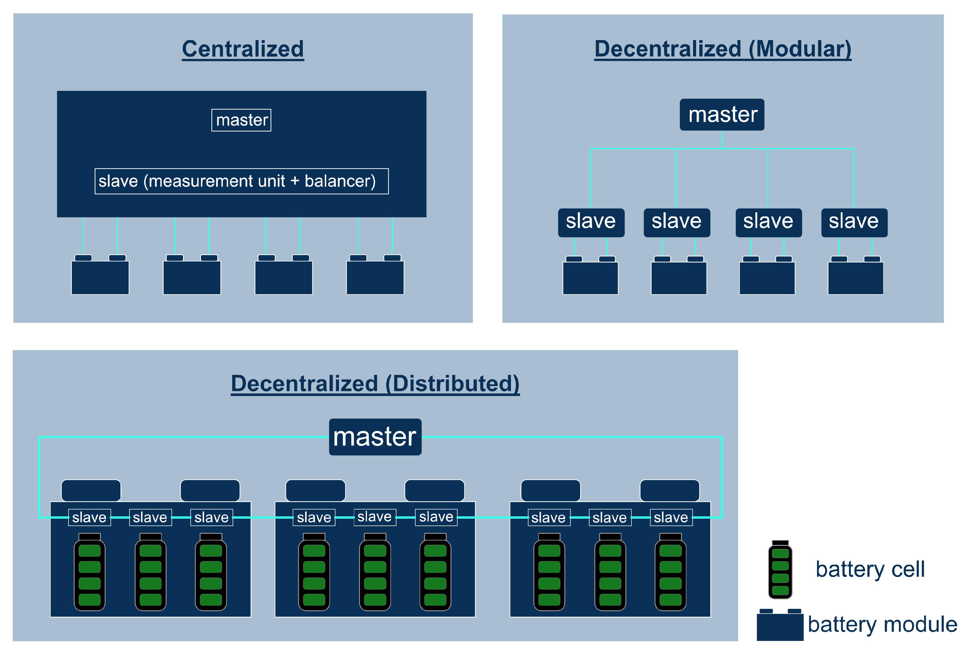
The physical layout of BMS hardware has a direct impact on scalability, fault tolerance, and wiring complexity.
- Centralized BMS: A single PCB monitors all cells. Lowest component count and cost. Wiring harness complexity grows O(n) with cell count; the long voltage sense wires are susceptible to EMI. Practical upper limit is approximately 96 cells in series.
- Decentralized Modular BMS: A master unit connects to multiple slave boards, each responsible for one module (typically 12–16 cells). The master-slave interface uses isoSPI, CAN, or a proprietary daisy-chain. This architecture scales cleanly to 400V–800V platforms.
- Decentralized Distributed BMS: Each slave board is physically embedded within its cell group. The highest fault isolation, best EMI performance, and greatest scalability. Preferred for commercial EV and stationary storage platforms where reliability is paramount.
Modern high-voltage EV platforms — 400V (e.g., mainstream passenger EVs) and 800V (e.g., Porsche Taycan, Hyundai Ioniq 6 GT) — invariably employ distributed or modular BMS architectures to meet ASIL-D requirements under ISO 26262.
EV Performance and the BMS Relationship
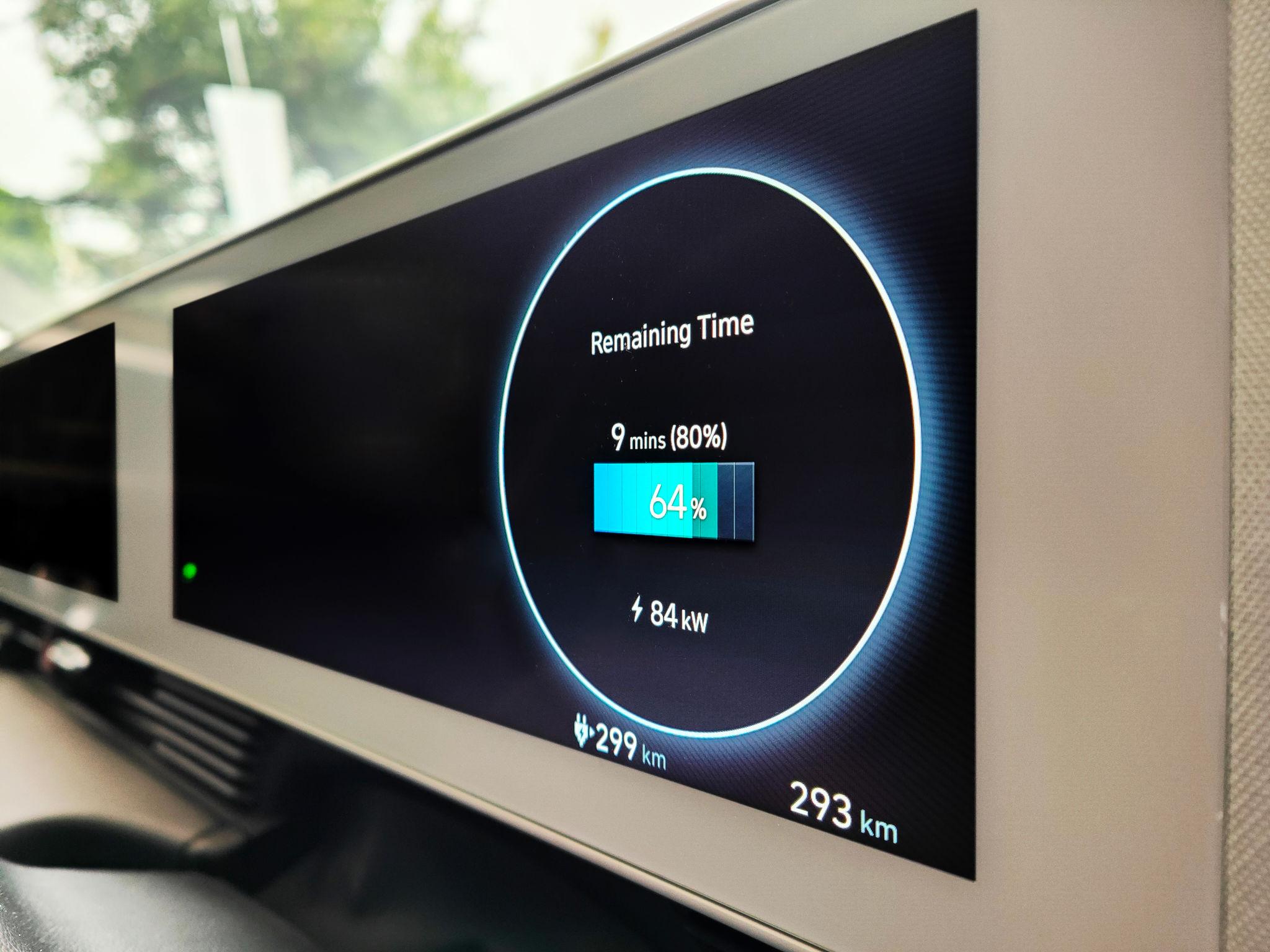
The BMS is not only a safety device — it is an active performance enabler. A well-designed BMS:
- Extends driving range by accurately estimating usable SOC, avoiding conservative safety margins that leave energy inaccessible.
- Maximises regenerative braking recovery by dynamically computing the maximum acceptable charge current based on current SOP.
- Optimises charge times through multi-stage CC/CV protocols adapted to real-time temperature and SOH — reducing total charge time by 15–25% vs. static protocols.
- Extends pack life by enforcing balanced cell usage, precise temperature management, and SOH-aware depth-of-discharge limits.
Future Outlook: AI-Enabled Intelligent BMS
BMS technology is advancing rapidly along several converging vectors:
- AI-based SOC/SOH estimation: Machine learning models (LSTM, transformer-based) trained on fleet data outperform Kalman-filter approaches in generalizing across temperatures and ageing states. Field accuracy targets of ±1% SOC are emerging.
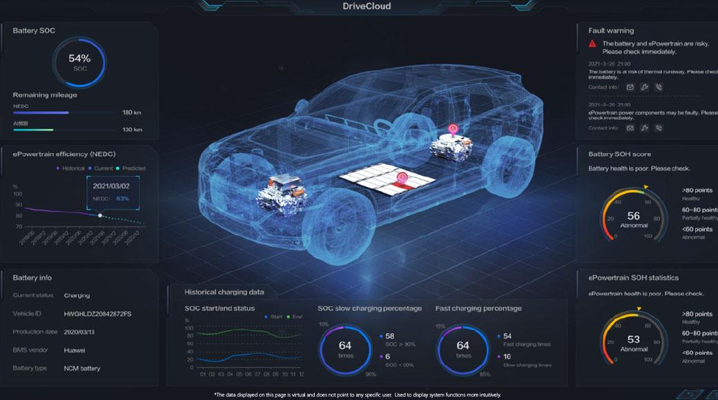
- Predictive battery analytics: Cloud-connected BMS transmits operational telemetry to backend platforms. Anomaly detection algorithms flag cells trending toward failure weeks before a protection event would occur.
- Digital twin integration: A live digital model of the battery pack — calibrated continuously against real measurements — enables simulation of remaining useful life, second-life valuation, and virtual commissioning of new chemistries before hardware production.
- Cloud-connected fleet BMS: OTA parameter updates, remote diagnostics, and fleet-wide learning (federated ML) allow BMS behaviour to improve across the installed base without hardware replacement.
Conclusion: The Critical Layer of Modern Electric Mobility
The Battery Management System forms the foundational layer of safe, efficient, and sustainable electric vehicle operation. As battery chemistries evolve — from NMC and LFP toward solid-state — and as pack voltages climb toward 800V and beyond, BMS complexity and criticality will increase in parallel.
Electric vehicle performance is not determined by battery capacity alone. It is determined by how intelligently that capacity is managed. In this context, the BMS is one of the most critical technological layers in modern electric mobility — and its engineering depth will define the competitive boundaries of the next generation of EVs.